QO-100 Build: Part 1 – The Design
Figuring out the shopping list
I think I first heard about QO-100 when looking at a local amateur’s QRZ page. He’d setup a couple of satellite dishes in his garden and had his QO-100 DX Club logo on his profile page, along with some other links. That started me down the rabbit hole. 🐇🛰️
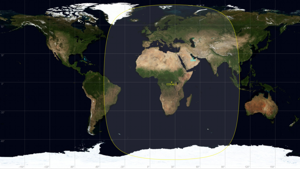
Briefly, and there’s more details here, QO-100 is the name given to a geostationary satellite that sits above Africa and has amateur radio transponders. This means it’s always in the same place, and can be used by amateur radio license holders to make contacts across its coverage. Being in such a high orbit means it has a huge area of coverage, so you can contact anyone in this area and talk to them for hours without the worry of propagation changing and losing contact.
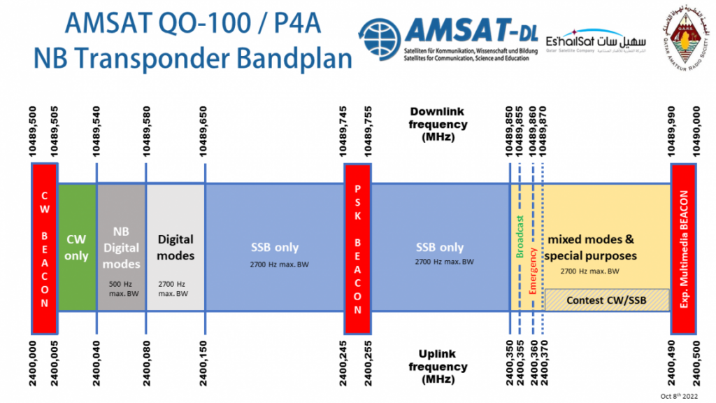
Another thing that makes this interesting is that it has both narrow and wide bands. This allows for voice, Morse and simpler digital modes on the narrowband and then on the wide band amateur television! So people can broadcast video via the satellite, there’s even a weekly net by the British Amateur Television Club (BATC), and they sometimes save them to YouTube. Doing video broadcasting requires a lot more equipment and power, and is maybe a step too far for me.
The satellite has been in orbit for about 5 years, so there are a lot of tutorials and guides online on how to get setup, together with people making items that help get connected. The main ones I found useful where DK1MI’s, M0AWS’s, and G7IYK’s Instructables page. My setup is basically the same as DK1MI and G7IYK’s, which I’ll explain shortly.
There seems to be two approaches to getting on the air with QO-100, one is via a SDR that can transmit as well as receive and the other is a transverter that takes you transmitter’s 2m or 70cm output and ups it to the send frequency. This means you can use a real radio to transmit. You can then either use a SDR for receive or use a downconverter and have your radio be the Rx as well. As I don’t have a 2m/70cm radio, and the location of my dish is not conducive to using a radio, I went with the SDR option, as that means everything can be housed in a box underneath the dish and all I have to run to it is power and ethernet.
Like most satellites the uplink and the downlink are on different frequencies, in this case it’s an uplink of 2.4 GHz (think wifi) and downlink is 10 GHz. The downlink is fairly easy, as a LNB (think Sky dish) can receive it and converts it down to 700 MHz range. This is perfectly fine for most SDR receivers to use. Uplink generally requires some amplification as either the upconverter or the SDR only outputs at very low power…but now we’re getting too into the detail.
My Plans
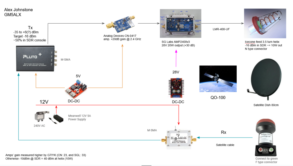
My in a loose sense of the word as it’s pretty much copying what many others have already done and figured out. I just found it useful to layout so that I could make sure I had all the right parts, particularly on the power side. I also attempted to figure out the power on the transmit side. Original version here.
The Receive
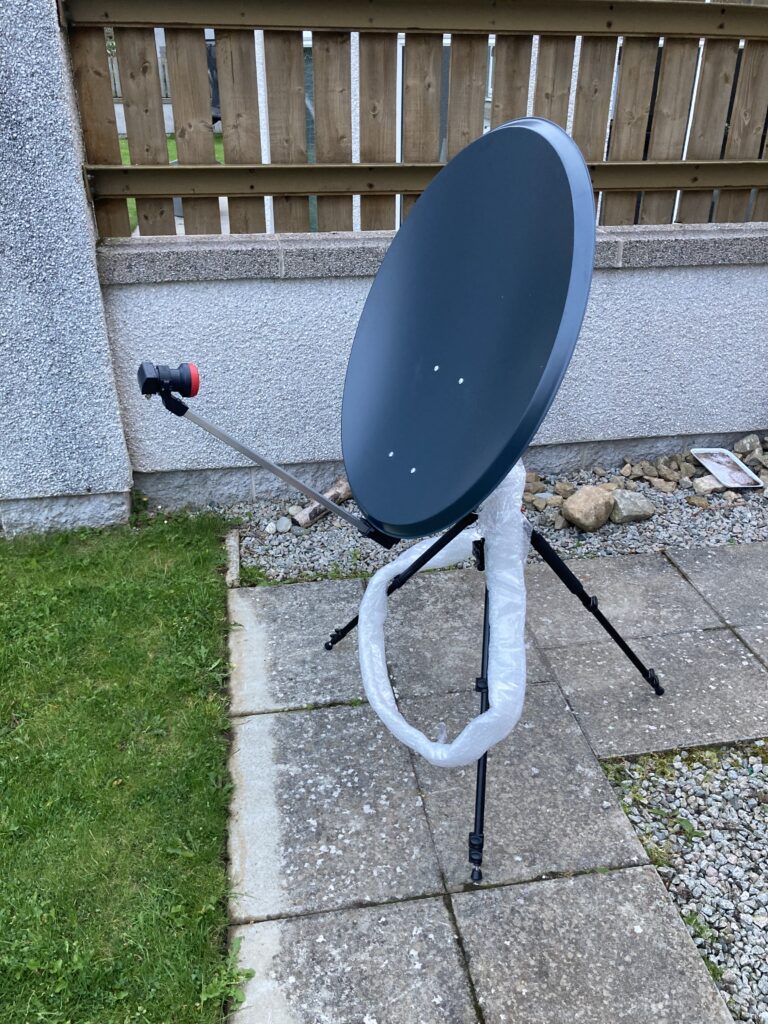
You’ll want a dish. I mooned over a 1.2m dish for a long time, but the price and size meant it was a no go for me. 80 cm seemed a common size for narrowband, and wideband probably wants something bigger than 1.2 anyway. I measured up where I was planning on putting it and 1.2m was probably too big, maybe I could of squeezed in a 1m but 80 cm should be good enough.
When thinking about what dish size, it’s important to think about the location of it. The satellite is to the south from the UK, near enough the same direction as sky dishes – a good guide if you or neighbours have on. You can get dish pointing info from the BATC on their website. So you can drag a pin around to place it exactly where you want it.
I originally wanted it on a south westerly wall but it probably would’ve ended up being mounted at 90° and that would mean being at least 40cm off the wall – perfect for a gust of wind to rip it off! However, I’m lucky enough to have a south-ish facing wall at the back of my house and so it was okay to find another location. I also bought a U shaped mount, so it could sit flush to the wall, which helps with wind loading and keeping it out the way.
The signal is focused onto a LNB (low-noise block downconverter). According to the internet, the Bullseye LNB is the “best” one. It’s fairly cheap, ~£30, and stable. In order for it to recieve the signal, a voltage has to be applied for polarisation of the signal. In our case, for the narrowband we need it to be vertically polarised and so applying 12V is what’s needed. This is done with a handy biased tee, that allows you to inject the voltage to the feed from the LNB, but blocks the DC voltage from continuing on to your recevier. I used satellite cable, the typical f type connector, 75 ohm stuff.
That’s it! The signal then continues to your SDR, in my case the Pluto+ SDR. A cheap SDR like a RTL-SDR or NooElec will do the job. As I said, a(nother) downconverter is an option but not the route I took.
Pluto+ SDR
Now’s a good time to talk about this SDR. First came the Adalm-Pluto by Analog devices. A great SDR which has transmit and recieve and ideal for students and amateurs alike. Many people use this SDR with great success and many have modified it themselves to improve it.
The Pluto+ is an upgraded version of Analog device’s SDR with various improvements available out of the box. Most noticeable are the metal enclosure, the four SMA connections, for two sets of recevie and transmit, a gigabit ethernet connection, a microSD slot, a external clock input on the PCB, and 0.5 ppm TCXO. Probably there are other tweaks too but not things that stood out to me. To me the biggest selling point was the network port and the relative ease at which you can add a GPSDO for stability (not something I had as part of the original plan but a nice blog post from DK1MI again shows how easy it is to add).
In my hours of searching and reading forums I recall coming across something like “if you’re building on from scratch go for the Pluto+”, and so I did. I bought mine from Aliexpress.
Tech Minds has a nice video on it if you want to see more.
The Transmit
The Pluto+ SDR has a transmit and can output 2.4 GHz in the region of up to 4 mW, which is great but also not going to get you a contact, and so some amplification is needed. These days it’s pretty much a standard design to use the Analog Devices CN-0417 amplifier straight out of the SDR and then another one to take it to up to 20 W. It seems like you really only need 10 W with a 80 cm dish to get a strong signal. In fact, if you transmit with too much power you hear a two-tone siren going off called LEILA warning you to turn down. A popular amp is the SG Labs 20W model from Bulgaria, and so that’s what I picked. 20W seems useful to overcome and losses in connectors and cables.
Which brings to me to cables. At 2.4 GHz, losses are high on regular coax (RG58/213) and so you really want some fancier stuff. I went for LMR-400-UF (UF for ultra-flexible to get round corners). It has many layers and is quite something to hold after only ever using RG58 on HF. You also want to keep it as short as possible and so the amplifier needs to be near your dish.
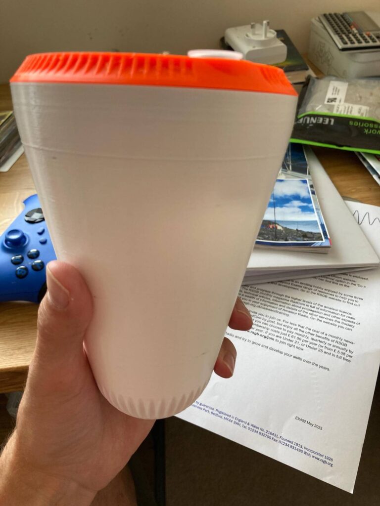
Finally, the actual feed to the dish. There seems to be two or three styles people use, a “POTY” or a helix seem most common. I felt like there were a lot of pieces to this build and so I wasn’t wanting to build everything myself, I decided to buy an Ice Cone feed from nolle engineering in Germany. This is a helix design, housed in a 3D printed case that looks like a huge ice cream cone. It’s designed very well and sits on top of the LNB (they even sell adapters for the most common LNBs people use with QO-100).
Power
All these bits and bobs need power, and at different voltages:
- The biased tee needs 12 V
- The Pluto+ SDR and CN-0417 need 5 V
- SG Labs PA needs 24-28 V
Again, as a common build, people have found a common solution, particularly as a lot of people power it from their shack power supply, and everything hangs off a 12 V supply. There are two DC converters, one to 5V with USB sockets for those users and then one that converts to 28V (although is adjustable) from 12V.
For me, and the location of my shack and the dish meant I needed an external power supply. Luckily, I have an external power socket within 5m or so of the dish so I just needed to convert it to 12V. In the end I decided upon a Meanwell power brick – think laptop brick – which gives up to 5A on 12V, this should be more than enough. I also bought a great long kettle lead to plug it in. Going for the brick meant it could sit in my waterproof enclosure with everything else. Plus the 5V DC converter had a pin socket, so I could use the pin from the power supply to power it and then the input pins, which are in parallel, for transferring that 12V on to the other users.
For the enclosure I found this on screwfix. It’s just about big enough. The mounting isn’t great but works.
Cost
It’s quite pricey to do this build. Part of me doesn’t want to list it all here and add it up 😅 However, as I didn’t have a 70cm/2m radio this route was probably going to be the cheapest. I could’ve scounged more on items, or tried to find more things used, but insted I bought the parts over about 6 weeks, then when it was only one £100-150 thing a week it didn’t feel that bad! Ballpark is probably £600-700. I also ended up buying some tools and general items that I didn’t have, but will be useful for other projects.
and finally…
Have I built it yet? I have, (and maybe why I struggle with tense in this post!) it still has a couple of issues but I’ve made some QSOs. More details in the next part.
